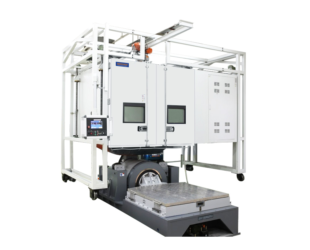
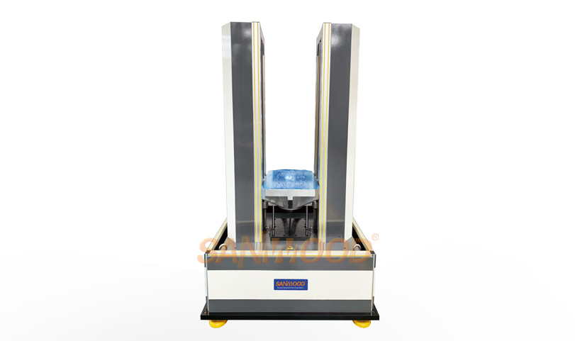
Pneumatic Vertical Shock Bump Test System
Product description
Pneumatic Vertical Shock Bump Test System is featured with advanced design, high degree of automation and reliability, simple operation and convenient maintenance. The system meets the requirements of both shock and collision test, can perform conventional half-sine wave, post-peak sawtooth wave, square wave and other waveform shock tests.
Pneumatic Vertical Shock Bump Test System is featured with advanced design, high degree of automation and reliability, simple operation and convenient maintenance. The system meets the requirements of both shock and collision test, can perform conventional half-sine wave, post-peak sawtooth wave, square wave and other waveform shock tests.
Features
-
Pneumatic drive, simple structure and high reliability
-
Pollution free, without hydraulic leak risk and keep the environment clean.
-
Pneumatic drive greatly improves the shock test efficiency, maximum shock rate up to 120 times / min.
-
It can easily realize large pulse width and small overload test.
-
With a fast shock rate comparing to motor or hydraulic driven collision table, it has higher reliability and better collision waveform.
-
The speed and rate of shock can be easily controlled by adjusting the gas pressure.
-
SM90 series shock control and measurement system can perform manual shock, continuous shock, single shock, and interval shock.
-
Built-in brake mechanism ensures the safety of operation in any situation.
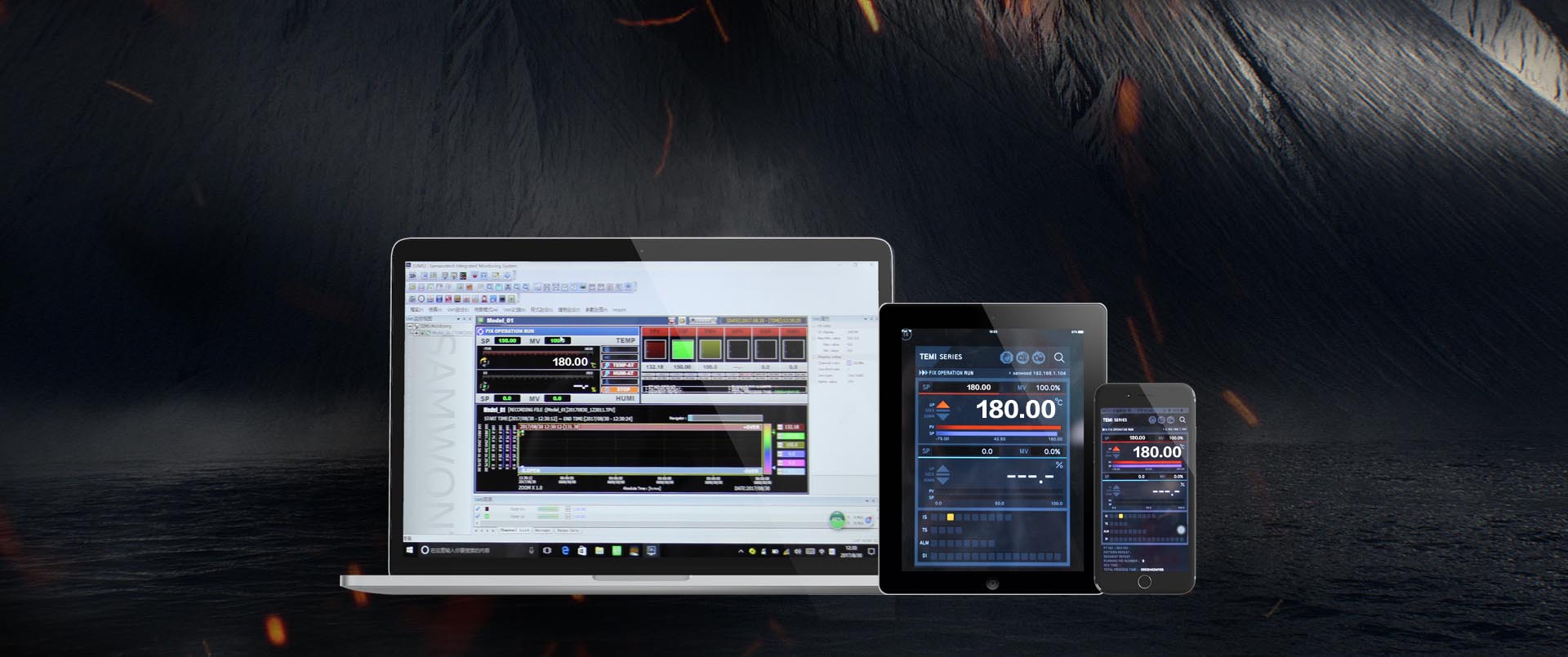
WE APPLY THE CONTROLLER DEVELOPED BY SANWOOD
parameter
| Model | SM02-25 | SM02-50 | SM02-100 | SM02-200 | SM02-400 | SM02-600 | SM02-800 | SM02-1000 | SM02-2000 | |
| Parameters | ||||||||||
| Rated Load (kg) | 25 | 50 | 100 | 200 | 400 | 600 | 800 | 1000 | 2000 | |
| Table Size (mm) | 300×300 | 500×500 | 600×600 | 800×600 | 800×800 | 1000×800 | 1000×1000 | 1200×1200 | 1500×1200 | |
| Peak Acc. (G) | Half-Sine | 10~850 | 10~700 | 10~300 | 10~200 | 10~100 | ||||
| Post-Peak | 10~200 | 10~200 | 10~100 | 10~60 | 10~50 | |||||
| Sawtooth | ||||||||||
| Trapeziod | 15~100 | 15~60 | 15~50 | |||||||
| Pulse Duration (ms) | Half-Sine | 0.8~40 | 1~40 | 1.5~40 | 2~40 | 3~40 | 4~40 | 6~40 | ||
| Post-Peak | 3~18 | 6~18 | ||||||||
| Sawtooth | ||||||||||
| Trapeziod | 6~12 | |||||||||
| Bump Waveform | Half sine wave | |||||||||
| Bump Peak Acceleration | 50~1500 | 50~1000 | 50~800 | 50~600 | 50~400 | |||||
| (m/s2) | ||||||||||
| Bump Pulse Duration (ms) | 3~30 | |||||||||
| Overall Dimension (mm) | 1400×1200 | 1600×1400 | 1700×1500 | 1700×1500 | 1900×1500 | 1900×1500 | 2000×1500 | 1900×1800 | 2200×1800 | |
| ×2300 | ×2300 | ×2300 | ×2300 | ×2450 | ×2450 | ×2450 | ×2550 | ×2550 | ||
| Weight (kg) | 1000 | 1800 | 2500 | 2800 | 3800 | 4000 | 4800 | 5200 | 6000 | |
| Max. bump Rate | 100 | 80 | 60 | 50 | 40 | 30 | 20 | |||
| (Times/Min) | ||||||||||
| Power Requirements for | AC220V±10%,50Hz,2kVA | |||||||||
| Table | ||||||||||
| Power | AC220V±10%, 50Hz, 3kVA or AC380V±10%, 50Hz, 5kVA | |||||||||
| Requirements for | ||||||||||
| Air Compressor | ||||||||||
| Air Source | Air source output pressure is no greater than 1.0Mpa. If there is no air source in the lab, air compressor needs to be configured; if there is air source in the lab, and there is ahigh requirement for bump frequency times, a corresponding air tank needs to be configured. | |||||||||
| Conditions | ||||||||||
| Working Environment | Temperature range 0 ~ 40℃; Humidity ≤ 90% (25℃), non-condense | |||||||||
| Standards | MIL-STD-810F IEC68-2-27 | |||||||||